Ultimate Guide to Local Inference
Overview
This document details the data flow in LLM inference systems, covering model loading, GPU communication, memory hierarchy, and inference processes.
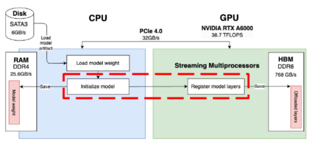
1. Model Loading Process
Loading Model from Disk to VRAM
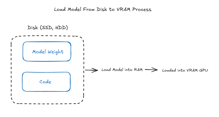
The process involves several steps:
-
Initial Storage (Disk)
- Models are stored on SATA/SSD drives
- Initial format includes model weights and code
-
Transfer Process
- Model is loaded into RAM first
- Subsequently transferred to GPU VRAM
- Direct loading to VRAM isn’t possible due to hardware architecture constraints
-
Memory Management
- CPU/RAM serves as an intermediary
- Model weights are loaded in chunks to manage memory efficiently
- VRAM allocation is optimized for GPU processing
Inference Execution Flow
When a prompt is received (e.g., “Hello, How are you?”), the system follows this process:
-
CPU Decision Point The CPU decides between two execution paths:
- Execute computation entirely on CPU
- Offload model layers to GPU for parallel computation
-
Execution Process

- Input data transfers from CPU to GPU
- GPU executes kernels on model weights
- Results are copied from VRAM to RAM (if needed)
- Post-processing occurs on CPU
-
Synchronization Considerations Critical sync points exist between Execute Kernel and Model Weight operations:
- GPU kernels run asynchronously by default
- CPU continues execution immediately after kernel launch
- Explicit synchronization prevents CPU from accessing results before GPU completes computation
2. GPU Communication Patterns
Flow 1: Direct GPU-to-GPU Communication
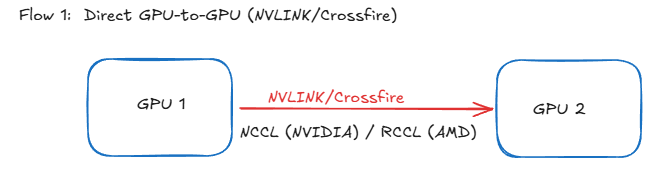
- Technology Used:
- NVIDIA: NVLINK/NVSwitch
- AMD: Crossfire
- Implementation Requirements:
- NVIDIA: NCCL (NVIDIA Collective Communications Library)
- AMD: RCCL (ROCm Communication Collective Library)
- Benefits:
- Higher bandwidth
- Lower latency
- Bypasses system RAM
- Direct memory access between GPUs
Flow 2: GPU-RAM-GPU Communication
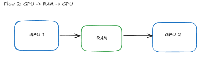
- Traditional Path:
- Data moves from GPU 1 → System RAM → GPU 2
- Performance Limitations:
- PCIe Bandwidth Constraints:
- PCIe 3.0: ~16 GB/s
- PCIe 4.0: ~32 GB/s
- PCIe 5.0: ~64 GB/s
- RAM Speed Limitations:
- DDR4: 25.6 GB/s
- DDR5: 38.4 GB/s
- HBM2: 307.2 GB/s
- PCIe Bandwidth Constraints:
3. Memory Hierarchy
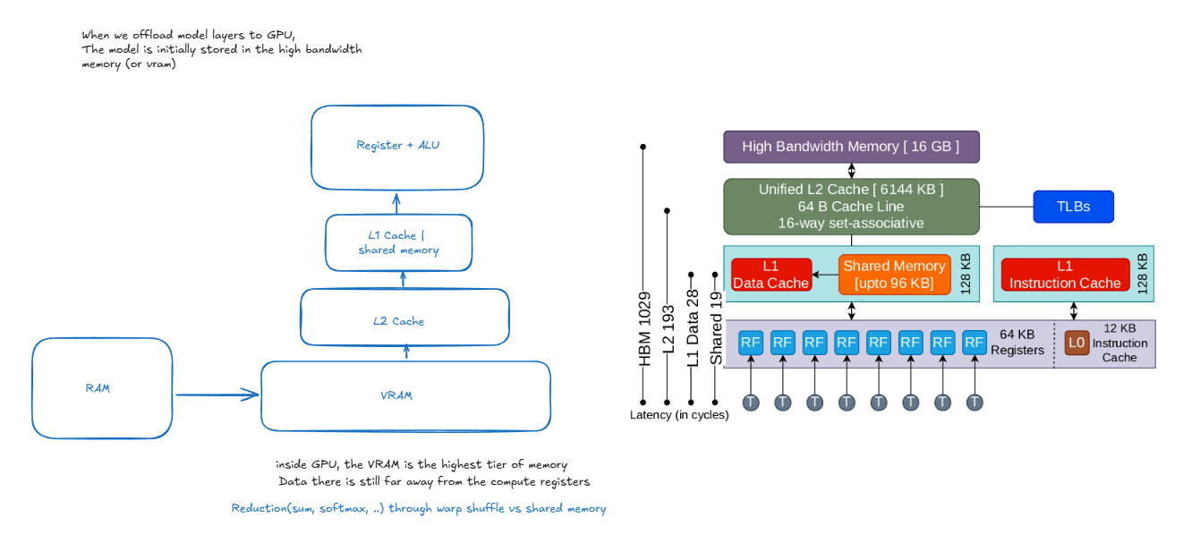
When offloading model layers to GPU, data traverses through multiple memory tiers, each with different access speeds and capacities. Understanding this hierarchy is crucial for optimizing LLM inference performance.
Memory Components
-
High Bandwidth Memory (HBM/VRAM) - 16 GB
- Primary storage for model weights and activations
- Connected directly to GPU via wide memory bus
- Bandwidth: ~900 GB/s - 1.2 TB/s
- Higher latency compared to caches (~400-600 cycles)
- Stores the complete model during inference
-
L2 Cache - 5144 KB
- Unified cache shared across all Streaming Multiprocessors (SMs)
- Acts as buffer between HBM and L1 caches
- Latency: ~193 cycles
- Caches frequently accessed model weights
- Helps reduce HBM access frequency
-
L1/Shared Memory Tier
-
L1 Data Cache
- Per-SM cache for fast data access
- Typically 128 KB per SM
- Latency: ~28 cycles
-
Shared Memory
- Programmer-managed scratchpad memory
- Same speed as L1 cache
- Used for inter-thread communication within SM
- Crucial for reduction operations (sum, softmax)
- Size configurable with L1 cache (shared pool)
-
L1 Instruction Cache
- Stores frequently executed instructions
- Reduces instruction fetch latency
-
-
Registers - 64 KB per SM
- Fastest memory tier (~1 cycle latency)
- Local to each thread
- Used for immediate computations
- Limited quantity per thread
Warp Shuffle vs Shared Memory
Warp Shuffle Operations
- Direct register-to-register communication within a warp
- Used for fast reduction operations within warps
- Zero memory access needed
- Common uses:
- Warp-level reductions
- Matrix multiplication accumulation
- Softmax normalization
- Limitations: Only works within same warp
Shared Memory Operations
- Visible to all threads in thread block
- Used for:
- Cross-warp communication
- Block-level reductions
- Cooperative data loading
- Higher latency than warp shuffle
- More flexible but requires explicit synchronization
- Better for larger data sharing patterns
Latency Hierarchy
- Register access: ~1 cycle
- L1 cache: ~28 cycles
- L2 cache: ~193 cycles
- Global memory (VRAM inside GPU): ~400 cycles
4. Inference Process
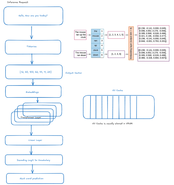
Request Flow
-
Input Processing
- Text input received
- Tokenization applied
- Vector conversion
-
Model Pipeline
- Embedding lookup
- Transformer layers processing
- Linear layer computations
- Vocabulary mapping
KV Cache Management
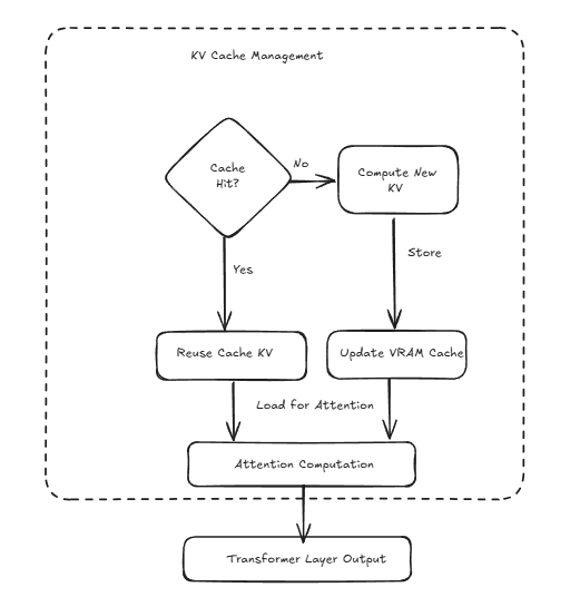
-
Cache Verification
- Check for existing KV pairs
- Evaluate cache hit/miss
-
Cache Operations
- Compute new KV pairs if needed
- Store in VRAM cache
- Update cache for attention computation
-
Memory Operations
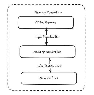
- VRAM memory management
- High bandwidth access patterns
- I/O bottleneck handling
Performance Considerations
VRAM vs RAM Speed Comparison